views
Blueprint Basics
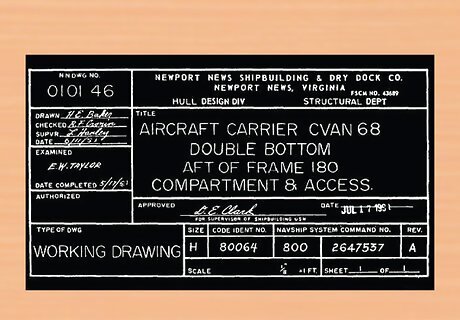
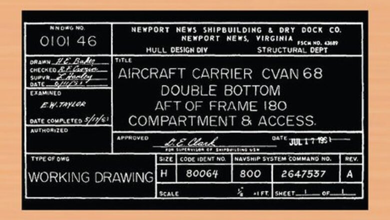
Read the title block. These often appear at the beginning of any blueprints. If you are involved in any serious construction work, you will want to make sure to read it all thoroughly. The title block's first section lists the blueprint's name, number, as well as the location, site, or vendor. If the drawing is part of a series this information will also be listed. This section is largely for filing and organizational purposes. The second section comprises bureaucratic information. Approval dates and signatures are located here. If you find a blueprint that interests you and want to know more, this information can be invaluable. Section three of the title block is the list of references. This lists all other drawings that are related to the building/system/component, as well as all blueprints that were used as reference/inspiration. Similar to the second section this can be incredibly helpful if you are to begin your own blueprint.
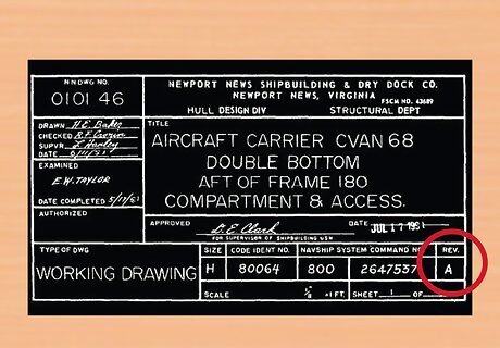
Read the revision block. Any time changes to a building/system/component are made, the drawing has to be redrafted. Those changes are listed here.
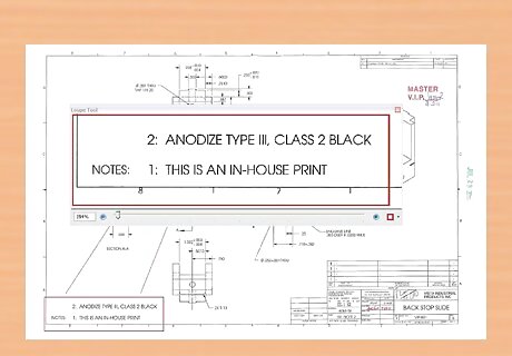
Read the notes and legend. In addition to the standard scale, grid, and lines, blueprints are often comprised of other symbols and numbers. In order to fully comprehend the specific blueprint you're working with, be sure to learn those symbols by reading through the legend. The notes will reveal any specifications or information the designer thinks will aid in understanding the drawing. For projects that actually begin construction it is even more important to read the notes. It's possible practical information like, "Do not begin working until 8am," will be listed.
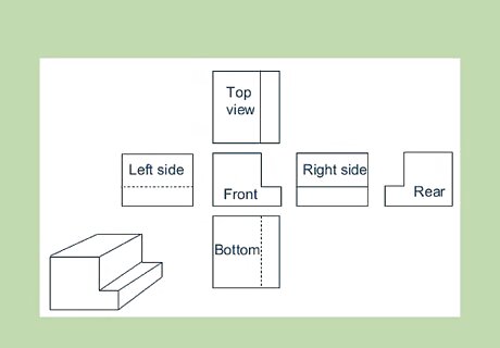
Determine the view. With 2D blueprints, there are three common perspectives: plan, elevation, and section. Understanding which one of these is being employed is an important first step to reading any drawing. Plan: A bird's eye view of planned work. Usually this is done on a horizontal plane at 30" above the floor. This perspective allows precise mapping of width and length. Elevation: A view of planned work from the side. These drawings are usually oriented from the north, east, west, or south. Composing an elevation map allows for detailed planning of height dimensions. Section: A view of something as if it were cut through. This perspective is generally imaginary, and is used to show the inner workings of how something will be built.
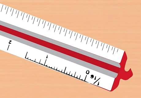
Establish the scale in your mind. Blueprints are scaled down representations of things like houses, underground piping, and power line. To ensure proper construction, always use precise measurements. The scale sets a rule for the entire drawing, saying what measurements on the drawing are equal to in real life. For example 1/8" = 1' (one eighth inch equals one foot). Architectural scales are used for the construction of building exterior and interiors; for establishing doors, windows, and walls. Many are presented in fractions: 1/4" = 1' (one-fourth inch equals one foot), 1/8" = 1' (one-eighth inch equals 1 foot). Engineer scales, or civil scales, are used for public water systems, roads and highways, as well as topographical endeavors. They use whole-integer ratios like 1" = 10' (one inch equals 10 feet) or 1" = 50' (one inch equals fifty feet). There are a variety of scales that might appear on blueprints. Common scales in the US include 1/4"=1' and 3/32"=1'.
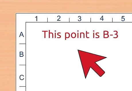
Inspect the grid system. Along the horizontal and vertical edges of a blueprint, drawers often fix a simple grid system with numbers on one axis and letters on the other. This allows anyone reading the plans to reference the location of a point or object within the drawing. For example, "let's take a look at the doorframe centered at point C7." If you are looking over the drawings with a team or partner and can't physically point to the location you're discussing, grid systems are very useful. This could be the case if you working online from different locations, or the other person/people simply isn't in the room with you.
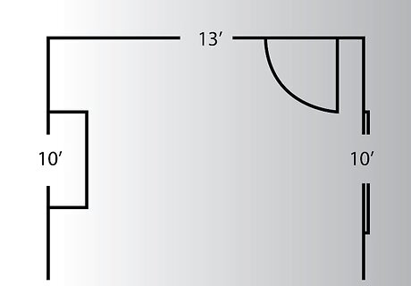
Locate any doors and windows. On blueprints, doors look like larger gaps between walls. There will also be a curved line with a mock door extended in or out of the door frame. This reveals which way the door will swing upon construction. Windows are likewise identified by the end of object lines and will typically be represented realistically to show their size. The blueprints should always include a door and window schedule. This will state the style, size, and material of each door and window.
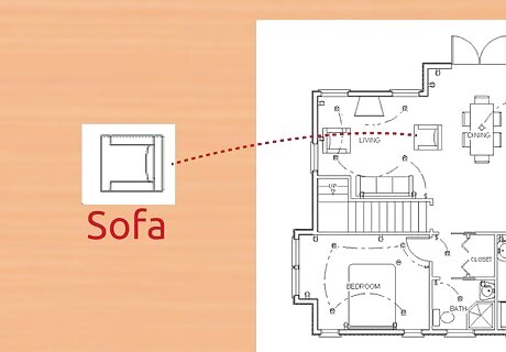
Identify any appliances. Fridges, toilets, sinks, ovens, stove-tops burners, and the like will be represented by simplistic representations that are readily recognizable. Take the time to consider whether they are located in an area where you want them. Although it may seem like their placement comes second the establishing walls, they can end up playing a more important role in deciding on design specifications. You should see the finish schedule included. This will tell you what style or model each appliance is.
Blueprint Lines
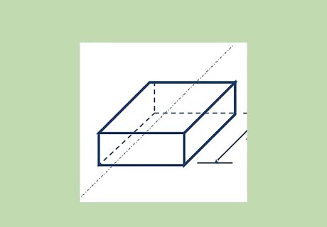
Look over the lines. Although it can seem overwhelming when taken in all at once, lines are the language of blueprints. Lines often represent walls, door frames, and appliance exteriors; however they have many other purposes and are the primary characteristic of planned drawings. Depending on their thickness, whether they are straight or curved, dashed or consistent, lines have different schematic significance. The type of basic lines are as follows: Object Line Hidden Line Center Line Extension and Dimension Line Cutting Plane Lines Section Line Break Lines Phantom Line
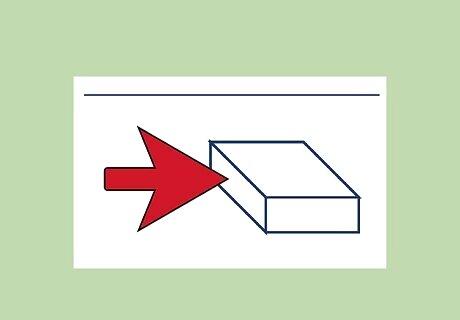
Identify all the object lines. Object lines - or visible lines - are drawn the thickest of all on a blueprint. They represent what sides of an object are visible to the eye. Consider a simple drawn cube, the only lines seen are those visible. On a blueprint, these take on an added importance; thicker than all others, they became the reference point to compare the weight and composition of all other lines.
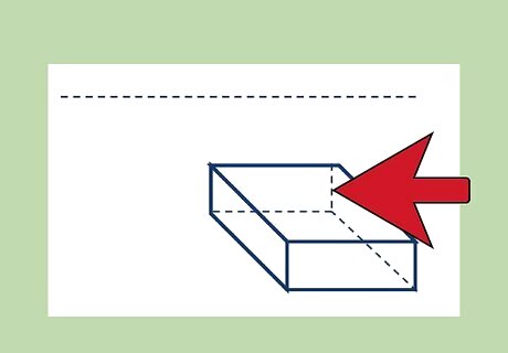
Identify the hidden lines. Hidden lines - or invisible lines - reveal surfaces that otherwise would not be visible to the eye. They are drawn at half the weight of object lines, with short, consistently spaced dashes. Consider the same drawing of a cube and how sometimes the otherwise invisible lines are represented in this same way. One rule of hidden lines is that they must always begin in contact with the line that is their starting point. The exception to this is anytime that first dash would appear to be a continuation of a solid line.
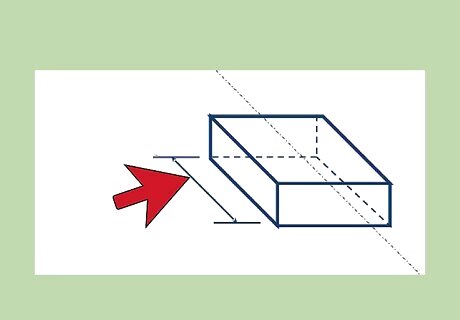
Read the dimension lines. Dimension lines show you the distance between any two locations in a drawing. Whether that be walls in a house, or the space between wiring in an electrical outlet. They are drawn as short, solid lines, with arrowheads on each end. The line's center point is broken, and here you will see the dimension (i.e. 3.5, 1.8, etc.) Dimension lines will help to envision a more 3D space and maintain correct spacing within a room or object.
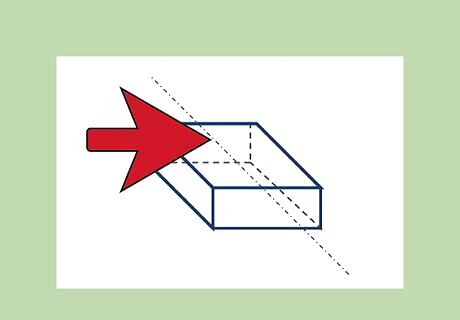
Find all center lines. Center lines establish the central axis of an object or part. You will most often see these with plans for circular or curved objects. On blueprints, they are drawn with alternating long and short dashes. Long dashes are on each end, and short dashes at points of intersection. Center lines are drawn with the same weight as invisible lines.
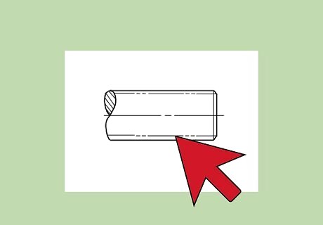
Find the phantom lines. Phantom lines are used to illustrate different positions of an object. For example think of a switch in the off position. Phantom lines could be used to represent its possible appearance in the on position. On blueprints you will see them drawn with one long and two short dashes, with another long dash on the end - all evenly spaced. Phantom lines also show any detail that needs to be repeated, or even the location of absent parts.
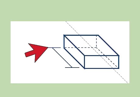
Identify extension lines. Extension lines are used to precisely define the physical limit of any dimension. They are drawn as short, solid lines, and can be placed inside or outside of the dimension being defined. Extending from the object outline, they do not actually touch the object lines. Since dimension lines often have to hover above an object simply because there is no room on the paper, or they would overlap, extension lines allow for more definite end and beginning points. Dimension lines are drawn with the same weight as invisible lines.
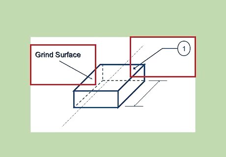
Locate the leaders. Leaders lines are solid lines ending typically in an arrowhead; these indicate any part or area of a drawing that is associated with a number, letter, note, or other reference. Desks, bookcases, and other furniture that don't come pre-assembled are a common reference to remember leader lines. In the instruction manual, lead lines are frequently used to define parts (i.e. "Place slot A into hole B").
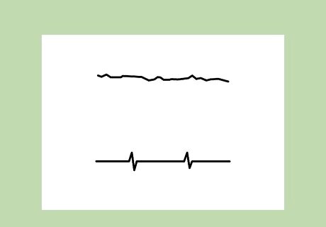
Read the break lines. Break lines are used any time a part is removed in order to reveal what lies immediately beneath. In architectural drawings they are often used when a long section of drawing have the same structure; this reduces the drawing size and saves paper. Short break lines are done freehand and resemble a solid, thick sin wave. Long break lines are long, thin ruler-produced lines interspersed with freehand zig-zags.
Further Education

Read books about blueprints. There are a number of general and trade-specific books on reading blueprints, some of which are published by hardware and tool-manufacturing companies and others by government agencies, such as the United States Army. These books are available in hard-copy and e-book formats. If you're interested primarily in architectural drawings, be sure to specify that in your searches. It's also possible to find blueprint lessons for maritime, civil, and engineering work in addition to many other fields.

Watch instructional videos. Videos are available in DVD format and as streaming Internet video. Many of the video tutorials available on popular viral streaming sites are uploaded by people with practical experience in construction and architecture. However some are presented by amateurs. Be sure to use discretion in self-learning online. Compare what you've learned to more formal academic sources that are also online. Youtube learning is a good place to start in your self-education because they can provide a more basic and grounding understanding, before you move into denser, more complex academic sources.

Take classes in reading blueprints. Blueprinting-reading classes are available at local trade schools and community colleges, as well as online. Universities teach many of the classes available online, but you can also learn from less expensive, specialized companies that only teach blueprint reading. Consider your budget when deciding which is right for you. Although learning online is convenient, you will definitely benefit from going to a community college, trade school, or University class. With an experienced teacher you can ask questions, bring in your work for review and receive consultation.
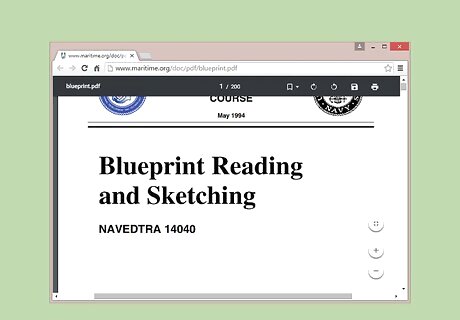
Learn to read blueprints online. In addition to providing access to classes and instructional videos, the Internet also offers a number of Web sites with information on reading blueprints. Although you won't receive any formal certification, all the resources you need to learn complex blueprint reading is available online. Read papers published by universities and experienced specialists so you can understand the language of architecture, and to make sure you're getting correct information. Balance this by reading and watching the materials produced by people who've experimented and self-taught. Be aware that they could potentially be presenting incorrect information, but also learn from their mistakes and experiences.


Comments
0 comment