views
Steps
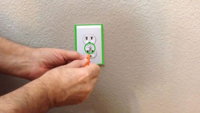
Make certain that the electricity is turned off to the circuit that you are working on. You should plug a lamp (test it first) into the outlet that you intend to change and then turn off the circuit breaker to make the lamp go off. If the device isn't working, find a different method to determine the power is off. If the outlet doesn't function at all, and you are not sure which breaker turns it off, then you may want to turn off the main breaker. This will shut down the entire house, but it is better to be safe than to risk electric shock. A voltage detector ("power sniffer") is also useful for detecting voltage. The light fixtures are usually on the lower value amp circuit breakers (usually 15 amps). If you leave the light fixtures on, it gives you better lighting to work on the plugs and switches. Standard outlets are usually connected to 15 and 20 amp circuits breakers. If the outlet in the room isn't protected by circuit breakers, but by fuses, make sure that fuse has been removed.
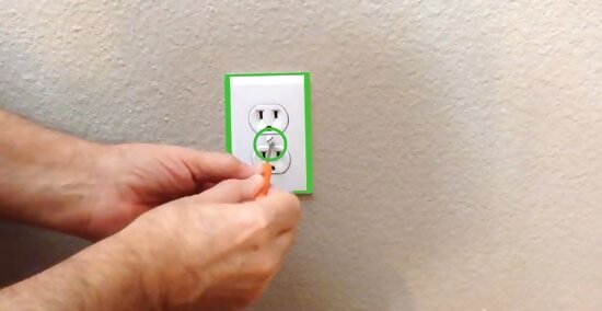
Remove the outlet or switch cover plate. Traditional outlet plates usually have one screw per outlet (but some - including GFCIs - have two) and switch plates two per switch. There may be multiple switches or outlets in one box, but you can replace just one if needed. If you need to replace more than one, work on each one at a time so that you do not confuse the wiring. Make a diagram (or take close-up digital photos) to have a clear record of how it looked before you disconnected anything.
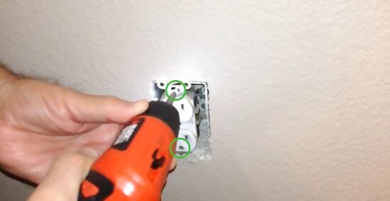
Find the two screws, one at the top and one at the bottom. These hold the switch/outlet to the electrical box. Remove these two screws and gently pull the switch or outlet out.
For outlets
Label the wires with some sort of identifying mark on masking tape wrapped around each wire. Use the same mark for each wire connected to the same terminal screw of the device. The "hot" (usually black or red) wires should be connected to the side that the shorter plug slot is on and generally have gold colored screws. The "neutral" white wires should be connected to the side that the taller plug slot is on and generally have silver screws. The bare-copper or green wire will connect to the green ground screw attached to one of the outlet mounting brackets. There may be one, two or more sets of wires connected to your outlet, depending on its location in the circuit. It does not matter which wire of a colored pair goes to which screw unless the outlet is controlled by a switch.
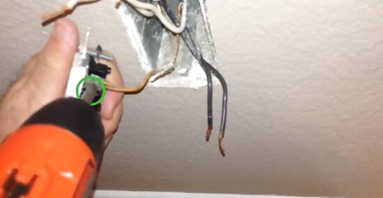
Loosen the screws on the new electrical outlet/switch where the wires will be held. Use a screw driver to open the screws until you feel you might have room enough to pull the wires on, so don't open them too much.
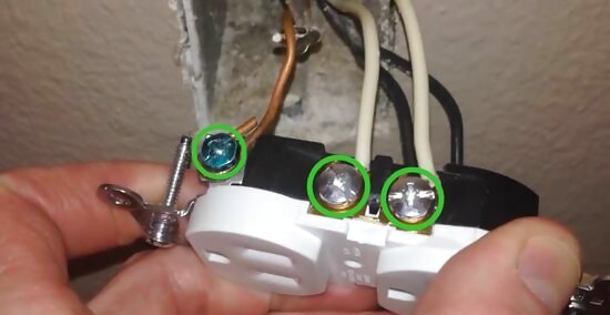
Connect the wires as was described in the step 1 of this "part"/subsection above. Make sure that the wires wrap around the screw completely without touching the plastic edges and without breaking off the tip of the wires themselves. Pull the wires around each of these screws until they are seated and won't disconnect if accidentally pushed backwards.
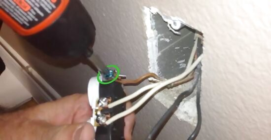
Tighten the screws, as you keep a firm hold on the outlet to ensure the wires don't slip. Tighten them until they are tight and the wires are touching the metal piece on the side of the outlet behind the screws.
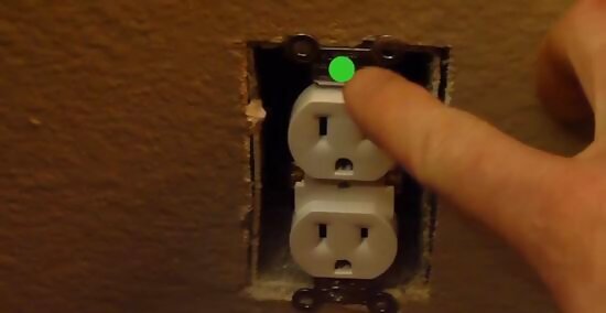
Push the electrical outlet back into the electric box. Make sure that the top screw tab is in line with their respective holes.
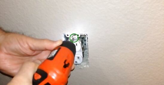
Screw the electrical outlet back into the box.
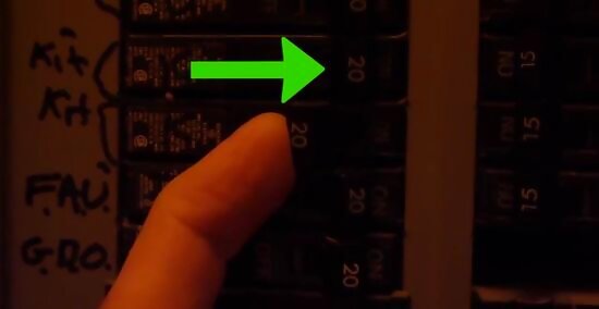
Turn back on the power, using any method as described above, turning on the breakers or reinstalling the fuses.
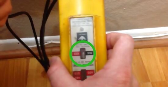
Test the outlet one more time. Use an small electrical appliance or one that won't draw too much power (such as a television set, computer system or mobile device), but be careful as open areas are now live. A better way to test an outlet is to use an electrical outlet tester. These can be purchased at your local hardware store, and usually cost between five and ten dollars. If the outlet tester reads "open ground", connect the grounding wire (green or bare) to the green grounding screw. If your home does not have grounding wires, you should replace the outlet with either a two-prong outlet or a GFCI outlet. If the outlet tester reads "open hot", connect the hot wire (red or black, unless re-identified) to the hot screw. If the outlet tester reads "open neutral", connect the neutral wire (white) to the neutral screw. If the outlet tester reads "hot/neutral reverse", switch the positions of the hot and neutral wires on the outlet. If the outlet tester reads "hot/ground reverse", switch the positions of the hot and ground wires on the outlet.
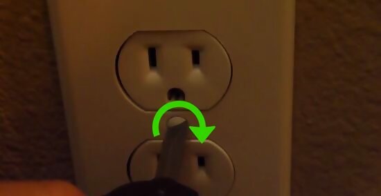
Remove the small electrical device and replace the outlet's cover plate.
For Ground Fault Circuit Interrupter (GFCI)
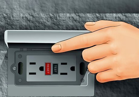
Make sure the following devices are connected to GFCI. For Ground Fault Circuit Interrupter (GFCI) receptacles (these have "Test" and "Reset" buttons and are required in bathrooms, garages, outdoors, and other locations within 6 feet of a water source, such as plugs serving counter top appliances near a sink in kitchens). Label the wires with some sort of identifying mark on masking tape wrapped around each wire. Use the same mark for each wire connected to the same terminal screw of the device. #* Look for an indication of "LINE" and "LOAD" on the body of the plug near the terminals. Each LINE and LOAD side has a gold and silver screw. It is very important to pay attention to this detail. Power source hot (most likely black or red) must connect to the LINE gold screw. Power source neutral (most likely white from the SAME cable carrying the power source hot) must connect to the LINE silver screw. A GFCI receptacle can provide "downstream" protection to other receptacles. For example, a GFCI in a kitchen may protect one or more other kitchen receptacles. If you have other "downstream" devices that are wired so that they are protected by the GFCI receptacle, there will be another cable(s) in the box. The cable(s) that feed the protected downstream plugs must be connected to the LOAD gold and silver terminals, and also the ground (green) terminal. If you connect any of these wires incorrectly, you will lose ground fault protection and/or damage the device.
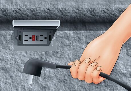
Determine which devices are not connected to GFCI. Some devices should not be connected to GFCI receptacles because of the possibility for "nuisance tripping"; for example, refrigerators, fluorescent lights, laser printers, garbage disposals, trash compactors, dishwashers, clothes washers and dryers, home heating and cooling systems, artesian well and driven point jet type pumps,microwave ovens and freezers are some of the more commons items. For switches: Label the wires with some sort of identifying mark on masking tape wrapped around each wire. Use the same mark for each wire connected to the same terminal screw of the device Determine the type of switch you have. A single-pole switch (one switch controls the light fixture(s)) will have two screws and be marked "ON" and "OFF" if a toggle type, a 3-way switch (two switches control the light fixture(s), typically at each end of a stairwell) will have three screws, one of which is black, and a 4-way switch (three switches control the light fixture(s)) will have four screws, two of which are black. Both the 3-way and 4-way switches do not have "ON" and "OFF" markings. A "two pole" switch has four screws as well, but unlike the four way switch; has ON and OFF markings Do not confuse these two switches. You must use the same type of switch that you are replacing!
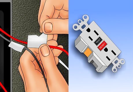
Make sure to mark each wire in the box per device with a label, and have the new replacement devices to connect. Regardless of the way it was wired when you opened the box, electrical device (receptacles, switches, etc.) terminals are designed for one conductor per terminal. Furthermore, outlets are not allowed to "complete" a circuit - this is sometimes called "daisy chaining". This means that you should not have to rely on the outlet to maintain power to the rest of the circuit. This is accomplished very easily by using wire nuts and "pigtails" (a 6 - 8 inch long piece of wire with stripped ends). Simply gather the wires that have the same identifying mark, and a "pigtail" and twist all of these wires together and secure them with a wire nut. Gently fold this wire nut bundle towards the back of the box, leaving the pigtail sticking out towards the front of the box. Put the same label on the end of the pigtail as those under the wirenut that you just put on. This is the new single wire that represents the group that was attached to the device when you started. Repeat this procedure for each wire with the same label. Obviously, if there are any wires that have unique labels, they should not be pigtailed, unless they are too short to easily connect to a terminal. After you have securely tightened the wires (wrap the wire clockwise around the screw, i.e., in the direction the screw turns as it tightens) to the new switch or outlet, gently push the wires back into the box and secure the outlet/switch to the electrical box. Inspect for damaged insulation / exposed conductors. Tape off exposed conductors. Do not wrap electrical tape over wire nut connections (the wire nut should stay on by itself if it is properly connected). Replace the cover and turn the electricity back on. Test the circuit to make sure it is functioning properly.


Comments
0 comment